
Fertilizer production
Fertilizer production
Highly efficient process to produce fertilizers from digestate.
In addition, high quality water that can be reused will is also obtained.
One of the most common ways of producing biogas is through the biodigestion of different types of organic waste. This biogas produced from waste can later be used in various ways:
- Production of electrical and thermal energy
- Biomethanation
- CO2 recovery
Biodigestion is a 100% sustainable and clean process, since it allows energy to be generated without the need of fossil fuels consumption.
However, a biodigestion process does not completely solve the problem of waste management, since the organic waste that it is used to generate biogas is transformed into a new waste called digestate, which must be treated as well.
The digested product, known as digestate, can be applied directly as fertilizer, but its low nutrient concentration and high volume make its handling difficult and costly, putting at risk the economic viability of the biogas plant development.
The BIODIGESTECH process solves this problem by recovering the digestate as a valuable product or by treating it to comply with discharge regulations.
System main data

Up to 100 m3/d of digestate.
Footprint 30 x 20 mts.
Installed power 250 Kw.
Water production 85 m3/d.
Fertilizer production 10 m3/d.
Up to 40 m3/d of digestate.
Footprint 20 x 15 mts.
Installed power 120 Kw.
Water production 34 m3/d.
Fertilizer production 4 m3/d.
Up to 3 m3/d of digestate.
Footprint HC40 container.
Installed power 15 Kw.
Water production 2.7 m3/d.
Fertilizer production 0.3 m3/d.
*Ultra-compact solution with combined SMBR and Reverse Osmosis technology.
Process description
The digestate from the biodigester accumulates in the storage tank where two pumps will be installed to feed the treatment system, one in operation and the other in reserve.
The treatment system consists in the concentration of the digestate. Prior to this process a pre-treatment will be necessary to reduce the suspended solids.
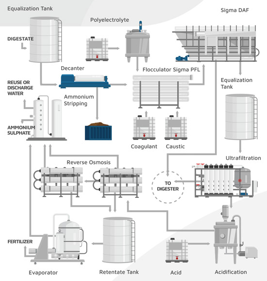
PRE-TREATMENT
Centrifugal decanter
At this stage, the digestate passes through a centrifugal decanter. The decanter allows the separation of coarse solids and sludge.
The clarified water is stored in a tank that has sufficient capacity for the operation of the following stages of the treatment. From this tank, the water is pumped with a centrifugal pump to the next stage of treatment, two pumps are installed, one in operation and the other in reserve.
Flotation clarification
Digestate often contains high concentrations of fine solids and suspended solids, which can reduce the performance of filtration equipment.
In this stage, fine solids and suspended solids are separated applying a coagulationflocculation process. Then, the water containing flocculated solids is treated using a SIGMADAF flotation clarification equipment. After this treatment, the values of suspended matter in the digestate are minimal.
Ultrafiltration
The components of the clarified water obtained in the pre-treatment, with a content of 0.2% of dissolved solids, consist mainly of nutrients: nitrogen, phosphorus, potassium, magnesium and sulphur.
At this stage, mainly colloidal matter, bacteria and viruses are eliminated. Ultrafiltration also ensures that there is no passage of solids to the next stages of the process.
At this stage, two flows are generated, on the one hand the permeate, which passes to the first concentration stage, and on the other hand a rejection or ‘retentate’, which is recirculated to the digester.
The ultrafiltration system is supplied mounted on a skid with a steel frame and made up of the following elements:
- Module with the corresponding ceramic membrane cartridges
- CIP cleaning system
- Feed pump / Recirculation pump
- Security pre filter
- Flowmeters, sensors, instrumentation, connections and valves
- Electrical panel
Dual Stage Reverse Osmosis
The permeate from the Ultrafiltration is acidified in a tank from which a centrifugal pump feeds it to the reverse osmosis equipment.
The main objective of this stage is to carry out a first stage of concentration of the pre-treated digestate.
In the reverse osmosis equipment, a 47% recovery is achieved, so the water is concentrated up to 1.8 times.The permeate can be reused, and the rejection contains nitrogen, phosphorus and potassium.
The osmosis equipment is supplied mounted on a skid with a steel frame and including the following elements:
- A 5 micron cartridge duplex filtration
- Meters of: PH, Redox, Temperature and conductivity
- A high pressure pump
- A booster pump for the second stage of RO
- Osmotic membranes
- CIP tank for flushing and chemical cleaning operations
- Electrical control panel of the unit
Evaporator
The reverse osmosis rejection must be stored in a tank from which the evaporation equipment is fed by suction.
In this equipment the rejection of osmosis is concentrated, approximately three times, until obtaining a distillate in which a part of the nitrogen escapes, for which a subsequent recovery system is proposed.
On the other hand, the concentrate is obtained. This concentrate retains nitrogen, phosphorus and potassium as well as the rest of the nutrients. This concentrate can be used as a liquid fertilizer.
Ammonium recovery system
Both the osmosis permeate and the evaporator distillate have nitrogen in ammonium form. This Nitrogen can be recovered obtaining a solution of ammonium sulphate (NH4)2SO4 with a richness of 40%.
The ammonium sulphate solution can be titrated separately or it can be mixed with the evaporator concentrate to obtain a final product richer in nitrogen. A stripping and scrubber system is proposed for the recovery of ammonium.
Both the osmosis permeate and the evaporator distillate are collected in a tank where the pH is adjusted to 10. By means of two centrifugal pumps, one in operation and the other in reserve, the stripping column is fed.
In the stripping column, the water with ammonium is fed through the upper part while the air passes through the bottom part. Inside the column there is a filling media that increases the contact between water and air. Ammonium passes from the water into the air.
The air stream is redirected to the gas scrubbing column. Air rich in ammonium is introduced at the bottom while recirculating an absorbent solution of H2SO4, at controlled pH. Once the ammonium sulphate concentration of 40% is reached, the product is discharged.
