- 1 1. Introduction: landfills for solid waste management
- 2 2. Concept of leachate, its control and collection
- 2.1 2.1. Control and collection procedures of leachate
- 2.2 2.2. Leachate characterization
- 3 3. Leachate treatment
- 3.1 3.1. Leachate transfer
- 3.2 3.2. Biological treatment
- 3.3 3.3. Physical-chemical treatments
- 3.4 3.4. Advanced treatments: membrane technologies
- 3.5 3.5. Conclusions for the different treatments applied to leachates
- 4 4. Technology applied by SIGMA to the treatment of leachate
- 5 5. References
03 May 2021
Leachate: efficient solutions for the environment. Proposed SIGMA technologies for leachate treatment.
Category:
1. Introduction: landfills for solid waste management
The generation of solid urban waste is directly related to the development and growth of human activity. Technological advances and growing urbanization have led to an increase in the consumption of products (food and other consumables, organic and inorganic, degradable and non-degradable, etc.) by the population and, as a consequence, contributed to an inordinate volume of waste.
Around one billion tons of solid waste is produced annually in the world and this figure is expected to continue to increase until reaching more than two billion in the year 2025.
These wastes have significant impacts on public health and the environment. When waste is not managed efficiently, it is a source of pathogens (insects, animals, viruses, bacteria, etc.), toxic agents and pollutants, from the soil and water.
The collection and storage in controlled landfills is one of the main forms of solid waste management. However, this supposes a localized contamination that puts at risk the quality of the soil and the water (both surface water and groundwater) near the landfill.
In the first fills that took place in landfills, it was a common practice to dispose waste by piling it uncontrollably in holes in the land, without regard for the surrounding environment, without care in the grouping of waste, without covers and without the adequate treatment of liquid seepage from the waste mass
These liquid infiltrations are the main topic of this article: leachates. Leachate can be defined as the liquid generated during the decomposition of the solid waste mass, added to the liquid infiltrated by rainwater and runoff that reaches the waste mass of the landfill.
This liquid waste is highly toxic and polluting for the environment and the living beings that inhabit it, including humans, the ecology and the food chain (crops, livestock, food processing and end consumers: people) and must be treated appropriately to its dangerousness. In addition to the solid waste itself, the derived liquid waste leachate, there is a gaseous waste: the biogas emitted into the atmosphere generated by the spontaneous fermentation of the organic fraction of the mixture of solid and liquid waste.
Nowadays scientific, engineering and economic principles are applied for the transformation and optimization of existing landfills, as well as for those that will be built in the future. The control and treatment of leachates is carried out as a crucial activity inseparable from the management of solid waste.
Currently, in many areas of economic powers such as the European Union and Japan are forced to manage solid waste through incineration, due to lack of space and as a definitive solution for the disposal of solid waste. However, this alternative involves severe air pollution due to the large emission of greenhouse gases, smoke, ash, volatile organic solids and other atmospheric pollutants.
This is a clear indication that there is no definitive solution for waste management, so management and treatment must be designed in a very rigorous way to prevent and reduce environmental pollution as much as possible.
2. Concept of leachate, its control and collection
A LEACHATE is defined as a contaminated liquid effluent that has leaked through the mass of waste deposited in a landfill whose characteristics and pollutant load are, in most cases, unpredictable, highly variable and highly dangerous for the environment.
Leachate is a compound of a combined nature, mineral and organic, formed when water infiltrates through the waste mass. This water can come from rain, snowmelt, irrigation water, underground water infiltration, runoff water, intrinsic humidity of the waste and liquid waste deposited in the landfill along with solid waste.
Water travels through the waste mass, extracting and dissolving pollutants, and serving as a medium for various chemical reactions and biological decomposition of these pollutants. The movement of water is favored by gravity, that is, it infiltrates from the outermost layers to the lowermost layers in the column of the waste mass.
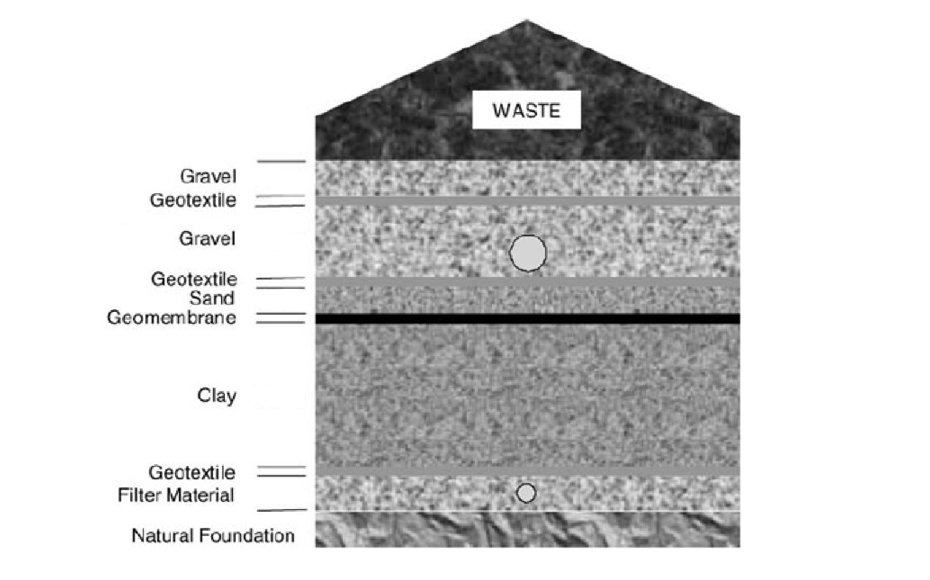
Under normal operating conditions of a properly designed landfill, the leachate is drained from the lower part of the waste mass by installing an impermeable layer and a network of leachate collection pipes and channels, which has to be directed to a point of storage and subsequent treatment.
If the leachate is not treated correctly, the landfill from which it comes can become a very dangerous source of hydrogeological contamination, given the risk of infiltration of the leachate into the soil and surface and groundwater.
2.1. Control and collection procedures of leachate
As the leachate forms and circulates through the waste mass, the organic and inorganic compounds dissolve and increase the contaminant load of the leachate.
In principle, this is a desirable effect since it frees the mass of waste from these pollutants, which would otherwise remain immovable and evolving in the solid, which could lead to future pollution problems and costs associated with their management.
If not properly treated, leachates are a dangerous source of contamination of soils, surface water and groundwater. In addition to being a source of contamination for the environment, leachates have a strong odor (especially young ones), so they require proper handling and transportation.
The most important points for optimal leachate management are:
- Correct and robust design of the landfill.
- Control and minimization of polluting liquids that enter the waste mass of the landfill.
- Installation and operation of a system for the extraction, collection and transport of leachates to the treatmen facilities.
- Installation and operation of a leachate treatment plant specially designed (considering factors such as the nature of the waste, age, climate, etc. as explained in the previous sections).
Control measurements that must be applied are:
- Establish a proper location of the landfill.
- Prevent the entry of liquid waste into the landfill through dumping bans.
- Apply proper landfill operating techniques.
- Apply runoff water control techniques.
- Install leachate collection and transport systems.
- Select, design and install an adequate leachate treatment.
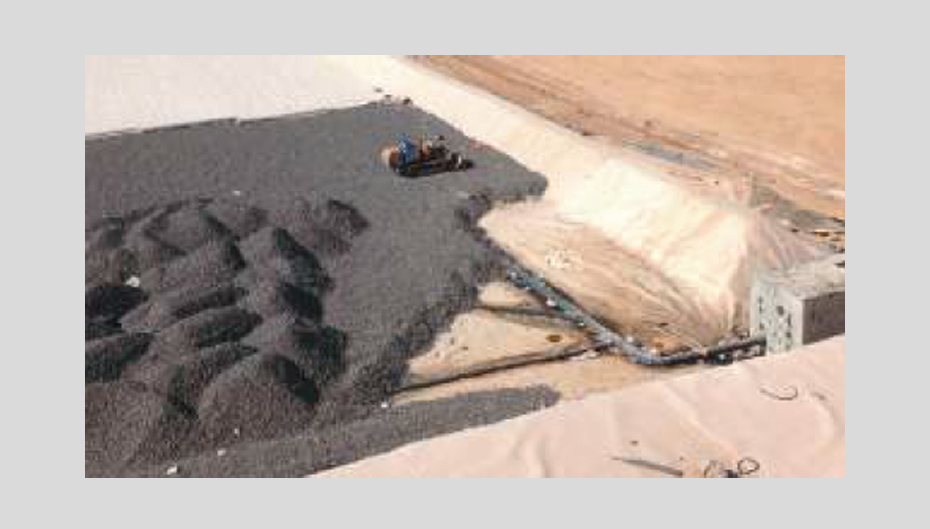
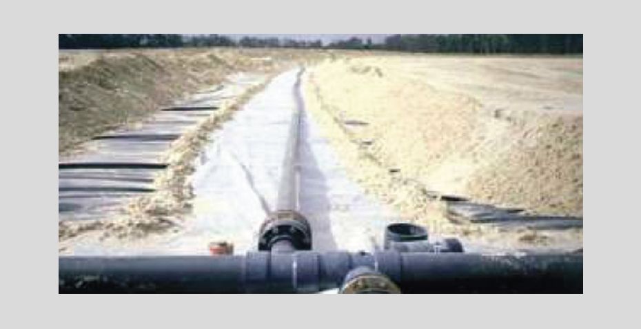
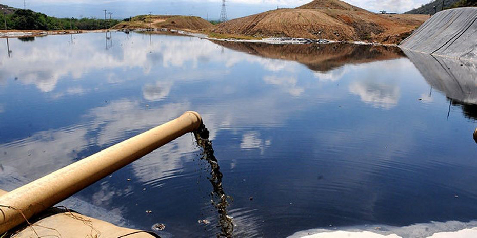
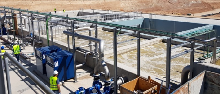
Figure 2. Collection and transport systems for leachates.
The type of treatment, its design, installation and operation depend on the characteristics of the landfill, since, depending on these variants, the leachate will have different characteristics that require specific processes and technologies for its treatment.
The characteristics to consider are:
- Size, age and future expansions of the landfill.
- Nature of the waste that accumulates and its moisture content.
- Climate zone: rainfall and temperature regime.
- Regulations and discharge laws that apply to the area.
- Possibility of dumping into a water body or into the sanitation network.
- Configuration of the facilities and availability of land.
- Budget available.
2.2. Leachate characterization
The composition of a leachate is highly variable and heterogeneous. The components that are generally found in a leachate are the following:
- High concentration of organic matter: chemical oxygen demand (COD), volatile fatty acids (VFA) and refractory organic matter such as humic and fulvic acids.
- Inorganic compounds: ammonia nitrogen (NH4+) resulting from the hydrolysis and fermentation of nitrogen from the biodegradable fraction of the solid residue, sodium (Na+), potassium (K+), chlorine (Cl-), calcium (Ca2+), magnesium (Mg2+), iron (Fe2+), manganese (Mn2+), sulfates (SO42-) and carbonates (HCO3-)
- Havy metals: cadmium (Cd2+), nickel (Ni2+), chromium (Cr3+), cobalt (Co2+), lead (Pb2+), copper (Cu2+), mercury (Hg2+ or Hg+) and zinc (Zn2+). They are found in concentrations between micrograms and milligrams per liter and have oxidation states that make them stable when dissolved in water.
- Xenobiotic organic compounds: aromatic hydrocarbons, phenols, pesticides, antibiotics and antivirals, medicines in general, micro-pollutants from hygiene and beauty products (makeup, soaps, shampoo, hair conditioners), household cleaning products (detergents, dishwasher, floor scrubber) and other similar products.
The composition of the leachate depends directly on: the nature of the waste it comes from, the age of the landfill, the water balance, the compaction of the waste mass, the moisture content of the waste mass, the climate, the geographical place where the landfill is located, the type of soil and topography on which the landfill is located, the vegetation surrounding the landfill, the operating conditions of the landfill and the reactions that occur within the waste mass (anaerobic digestion, adsorption, dissolution, ion exchange, redox reactions, precipitation).
Although the range of pollutants in a leachate is wide, there are two critical points when designing the treatment: the high concentration of recalcitrant organic compounds, due to their great difficulty in being eliminated with biological treatments, and the high levels of ammonia nitrogen NH4+ specially in leachates from young waste masses, due to the danger they are to the environment and their toxicity for biological treatment. High concentrations of NH4+ lead to the depletion of dissolved oxygen in natural water bodies (a phenomenon known as eutrophication) if the leachate reaches them, with the consequent death of the living beings that inhabit it and expansion of the contamination to other points in the water, aquatic network and ecosystem soils.
The age of the landfill is a determining factor since a large part of the compounds and characteristics of the waste change throughout the maturation process of a waste mass.
According to their age, the masses of waste from a landfill can be classified into three categories:
Young: less than five years, also named “acidogenic”.
Intermediate: between five and ten years.
Mature: more than ten years, also named “methanogenic”.
Table 1 lists the most important characteristics and ranges of the leachates according to the age of the waste mass from which they come, characteristics that will determine the design of the leachate treatment.
Table 1. Main characteristics of leachates according to the age of the waste mass.
Parameter | Young | Intermediate | Mature |
|---|---|---|---|
Age (years) | <5 | 5 - 10 | >10 |
pH | 3 - 6 | 6,0 - 7,5 | 7,5 |
COD (mg/L) | 50.000 - 10.000 | 20.000 - 4.000 | <5.000 |
BOD5 (mg/L) | 25.000 - 10,000 | 4.000 - 1.000 | <1.000 |
Ammonia nitrogen NH4+ (mg/L) | 4.250 - 1.500 | 700 - 250 | 200 - 30 o <30 |
Alkalinity (mg/L) | 18.000 - 8.000 | 6.000 - 4.500 | - |
Phosphorus (mg/L) | 300 - 100 | 100 - 10 | <10 |
Sulphate SO42- (mg/L) | 2.000 - 500 | 1.000 - 200 | 200 - 50 o <50 |
Total suspended solids (mg/L) | 25.000 - 10.000 | 10.000 - 5.000 | 5.000 - 1.000 o <1.000 |
Organic compounds | Mainly VFA (~80%) | 5-30% of VFA and the rest is humic and fulvic acids | humic and fulvic acids (recalcitrant compounds) |
Heavy metals load | Low - medium | Low | Low |
Biodegradability | High | Medium | Low |
2.2.1. Water balance on a landfill
The potential for leachate formation can be determined by means of a water balance that relates the water that enters the landfill, the water consumed in biochemical reactions and the evaporated water. The scheme in Figure 3 is proposed for the water balance in a landfill. The leachate flow depends on the amount of precipitation (P), runoff and seepage from outside the landfill (Rext), runoff and seepage from the landfill itself (Rint), non-desired infiltration into the soil (leachate leaks reaching the medium environment, I) and natural evaporation of moisture (E). The water balance can be established in general lines with the following relationship:
Leachate effluent = P + Rext + Rint - I - E
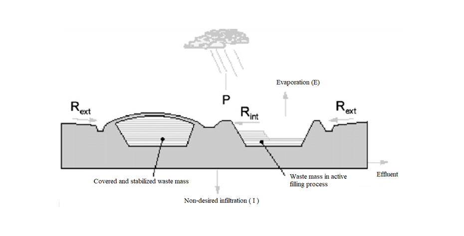
The correct design, construction and operation of the landfill and its drainage systems will reduce the production of leachate and the flow of unwanted infiltration into the soil.
2.2.2. Anaerobic degradation of the organic fraction of the solid waste in a landfill
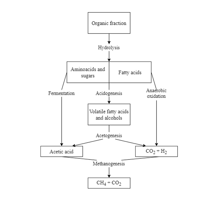
The composition of a leachate evolves as a function of time, following an anaerobic degradation process as shown in Figure 4.
Young landfills contain a large amount of biodegradable organic matter that allows very rapid anaerobic digestion, resulting in the production of VFA through acidogenesis as the main product. Acidogenesis is promoted by the high moisture content of the solid waste.
The main processes in an intermediate landfill are acetogenesis or fermentation (formation of acetic acid CH3COOH) and anaerobic oxidation (degradation to carbon dioxide CO2 and hydrogen H2) of the compounds accumulated during young age.
Methanogenesis takes place in a mature landfill. During this phase, the methanogenic microorganisms that have developed naturally in the waste degrade the compounds previously generated, transforming them into biogas (gas consisting of methane CH4 and carbon dioxide CO2).
The organic fraction that remains after anaerobic digestion and that remains in the leachate is mainly made up of refractory organic compounds, that is, they are not biodegradable, these are humic and fulvic acids.
3. Leachate treatment
After collecting and transporting the leachate, a treatment system must be established according to the characteristics of the leachate. It is remembered that each leachate must be treated according to:
- Its composition and pollutant load, which depends mainly on the nature and age of the mass of waste from which it comes.
- The flowrate to be treated, which depends on the water balance and how well managed the corresponding flows and drainage are.
The characterization of the leachate (analysis of its chemical composition and pollutant load) and a detailed study of the technologies to be applied are mandatory steps for each leachate in order to determine and design the treatment process.
The main objective of the treatment is the elimination of organic matter and ammonia nitrogen and suspended solids as well as other toxic compounds, as a fundamental requirement to comply with the legal criteria for the discharge of leachate into the sanitation network for its final treatment and discharge, or directly to a natural aquatic body (for which the pollutant concentration limits will be more restrictive). Also, a highly rigorous treatment can be established to be able to reuse the water back in process.
It is very important to understand that there is no universal treatment applicable to all leachates given their high complexity and variability.
Leachate treatments are generally classified into: leachate transfer (redirection of leachate to external treatment or other forms of management), biological treatments (use of biomass to remove contaminants), physical-chemical treatments (use of physical reactions and/or chemical products) and advanced treatments (application of membrane technologies).
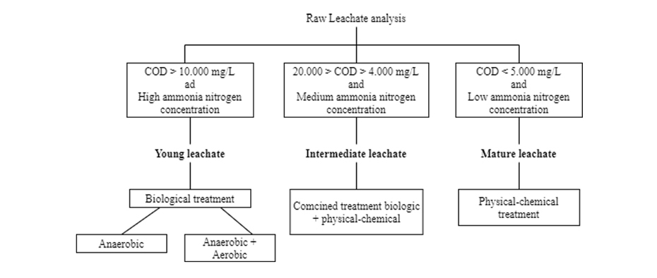
Figure 5 shows a general sequence of treatment choice based on its COD and ammonia nitrogen content.
Also, the design selection can be based on the following table, where some of the most commonly used processes are classified according to their efficiency with respect to the age of the leachate:
Table 2. Treatment efficiency of leachate according to its age. Adapted from Abbas et al. 2009 and Costa et al. 2018.
Treatment | Age of the leachate (years) |
| |||||
Young (<5) | Intermediate (5 - 10) | Mature (>10) | Main objective | Comments | |||
Transference |
|
|
|
|
| ||
Combined treatment with municipal wastewater | Good | Fair | Poor | Suspended solids | Biomass and nutrients excess | ||
Recycling | Good | Fair | Poor | Improving the leachate quality | Cheapest but less effective | ||
Evaporation | Good | Good | Good | Reduction of the leachate volume | Treatment for the concentrated waste is needed. Requires aerosol sprays and odours control. The natural process is slow and the thermal process is highly expensive | ||
Biological treatment |
|
|
|
|
| ||
Aerobic treatment | Good | Fair | Poor | Suspended solids | Hampered by refractory compounds. Generates excess of biomass | ||
Anaerobic treatment | Good | Fair | Poor | Suspended solids | Hampered by refractory compounds. Requires long reaction times | ||
Physical-chemical treatment |
|
|
|
| |||
Coagulation – flocculation | Poor | Fair | Fair | Heavy metals and suspended solids | High sludge production that requires further treatment | ||
Chemical precipitation | Poor | Fair | Poor | Heavy metals and ammonia nitrogen | Requires further treatment of the generated sludge | ||
Adsorption | Poor | Fair | Good | Organic compounds | Expensive. May be affected by biofilm formation on the activated carbon surface | ||
Chemical oxidation | Poor | Fair | Fair | Organic compounds | Ozone, chlorine and other non-desired sub-products are generated | ||
Stripping with air | Poor | Fair | Fair | Ammonia nitrogen | Requires gas treatment | ||
Ion Exchange | Good | Good | Good | Dissolved compounds, cations and anions. | Used as polishing after biological treatment. Very expensive | ||
Advanced treatment: membrane technology |
|
|
|
|
| ||
Microfiltration | Poor | - | - | Suspended solids | Applied after chemical precipitation | ||
Ultrafiltration | Poor | - | - | high molecular weight compounds | Expensive and limited by fouling | ||
Nanofiltration | Good | Good | Good | Sulphate salts and alkalinity ions | Expensive and limited by fouling | ||
Reverse Osmosis | Good | Good | Good | Organic and inorganic compounds | Expensive and limited by fouling. Requires always pre-treatment, generally Ultrafiltration. | ||
Biological processes are generally applied to younger leachates as they contain a large amount of rapidly biodegradable organic compounds. However, the high concentration of ammonia nitrogen and other toxic compounds in young leachates are an inhibitory factor for biomass, which is why a pre-treatment is necessary, the most used are physical-chemical processes.
Biological processes are not appropriate for the treatment of mature leachates as they contain large amounts of non-biodegradable or refractory organic compounds. For the more mature leachates, combined physical-chemical processes and advanced treatments with membrane technology are commonly applied.
It has been proven that biological or physical-chemical treatments alone are not capable of achieving the required removal efficiencies, so combinations of the two groups of technologies have to be used, which can be accompanied by advanced processes. The complete treatment train will always be specifically designed for each leachate.
3.1. Leachate transfer
Leachate transfer consists of managing, redirecting or evaporating it.
· Combined treatment with urban wastewater
It consists of channeling and pumping the leachate to the sanitation network for its subsequent treatment in an urban wastewater treatment plant WWTP. This management implies a low cost, low maintenance and low operational difficulty, since only a pumping and transport network has to be installed up to a point of mixing with urban wastewater and the payment of taxes for discharge to the public sanitation network.
The presence in the leachate of inhibitory compounds with low biodegradability and heavy metals can reduce the efficiency of WWTP treatment and increase the concentrations of pollutants in the effluent. As advantages of this management, it stands out that no extraordinary addition of nutrients is required in the WWTP since the leachate provides sufficient nitrogen and the urban wastewater provides sufficient phosphorus for the proper functioning of the biological treatments of the plant.
· Recycling
It consists of channeling and pumping the leachate to reintroduce it into the waste mass. This option is the cheapest of those presented since it simply requires the installation of the pumping system, entails low maintenance and low operational costs.
The recirculation of leachate results in an increase in the amount of moisture in the waste mass, which in turn causes an increase in the biogas production rate of the mass. Thus, a significant reduction of the COD is achieved that will be carried over in the generation of the subsequent leachate. However, excessive recirculation can adversely affect the anaerobic digestion of the waste mass.
In addition to improving the quality of the leachate, recirculation causes the time required for the maturation of the waste mass to be shortened to 2 to 3 years.
· Evaporation
Evaporation is a process of separation: the raw leachate is divided into steam and residues that contain the entire pollutant load of the leachate and that must be carefully managed.
The evaporation of water requires large amounts of thermal energy. Passive evaporation in lagoons uses solar energy and is not applicable to humid climates, as well as being extremely slow. Other more sophisticated systems such as closed evaporation units use external energy and are highly expensive.
Any evaporation system entails high operational costs, emission of strong odors and emission of aerosols. Given the high level of salts that leachates generally present, all installed equipment must be prepared to work in this corrosive environment.
3.2. Biological treatment
Biological treatments are known, reliable, simple and very cost-effective processes. The biological treatment is widely used with young leachates for the elimination of the high load in biodegradable organic compounds.
Biological treatment is carried out through the use of microorganisms that are capable of degrading organic compounds in carbon dioxide and sludge under aerobic conditions, and in biogas (methane and carbon dioxide) under anaerobic conditions.
In very high concentrations, ammonia nitrogen is toxic to microorganisms and can inhibit the treatment, which is why a physical-chemical pretreatment is required to eliminate this compound. Furthermore, these treatments are not recommended for mature leachates since they mainly contain refractory organic compounds that cannot be removed by biological degradation.
· Aerobic treatment
It allows the elimination of biodegradable organic pollutants and the nitrification of ammonia nitrogen.
Suspended biomass systems (aerobic)
Aerated laggons: efficient and low-cost systems for the elimination of pathogens and organic and inorganic matter. They are attractive due to their low maintenance and operational difficulty, especially in developing countries as they do not require a high qualification of the operators. For locations where there are strict treatment requirements, lagoon may not be a sufficiently effective treatment. It also has a strong dependence on temperature.
Activated sludge: It is widely applied in the joint treatment of leachate and urban wastewater, but it is unsuitable for the treatment of only leachate. Although this process has been shown to be effective for the removal of COD, ammonia nitrogen and phosphorus, it has too many disadvantages when applied to leachates: inadequate sedimentability of the sludge, need for very long aeration times, excessive generation of sludge, very high energy demand, inhibition of microorganisms with very high concentrations of ammonia nitrogen.
Sequence batch reactors SBR: it is ideal for nitrification-denitrification processes and allows a simultaneous operating regime of elimination of organic matter and elimination of ammonia nitrogen. Sludge sedimentation is performed in the same tank. It is a very flexible technology and is one of the most widely applied in leachate treatment, since this flexibility is compatible with the variable nature of a leachate.
SIGMA offers the design and construction of SBR reactors. These are robust equipment with very high reliability, easy adjustment and operation, and highly effective for treating medium volumes of industrial wastewater that require nitrification and denitrification processes. These plants usually have a previous physical-chemical process followed by one or more SBR tanks.
AGUASIGMA SBR systems use our dual AQJETS aeration equipment that allows the sequence of mixing in anoxia and aeration with a single mechanism.
Attached biomass systems (aerobic)
These technologies are based on the retention of biomass through biofilm. These technologies do not suffer the loss of active biomass, nitrification is less affected by temperature variations and by inhibition due to the high content of ammonia nitrogen.
Thrickling filters: these filters are highly interesting in the treatment of leachates since they allow the reduction of ammonia nitrogen and the cost of the filter medium is very low.
Moving bed bioreactor MBBR: the MBBR process is based on the use of porous polymeric material carriers that float in the reaction tank and where the active biomass grows attached to its surface, generating a biofilm. Currently there is a tendency to use granular activated carbon as a ‘carrier’. The main advantages of an MBBR are: higher biomass concentrations, no long sludge settling periods, low sensitivity to toxic compounds, simultaneous removal of biodegradable organic compounds and ammonia nitrogen. An MBBR system allows an efficient balance between adsorption and biodegradation processes.
The following table includes a collection of examples of real plants that treat leachates by applying aerobic reactors in their process. The table shows the available data such as the organic load of the leachate in COD, the operating temperature and the efficiency of removal of organic load.
Table 3. Operational parameters and real plant yields treating leachates with aerobic reactors. Adapted from Renou et al- 2008.
COD (mg/L) | BOD/COD | T (ºC) | Performance, as pollutant removal (%) |
|---|---|---|---|
Activated sludge |
|
|
|
4.000 (BOD5) | - | 20-25 | 51,3 TOC |
5.000 | 0,6 | 5-10 | >92 COD |
1.537 | - | - | 96 COD |
2.000-4.600 | 0,41-0,59 | 21 | 46-64 COD |
3.176 | 0,33 | 25 | 59 COD |
2.900 | 0,66 | 24 | 75 COD |
5.000-6.000 | - | 25 | 97 COD and 87,5 NH4+ |
3.130 | 0,56 | - | 69 COD |
270-1.000 | - | 5-10 | 50 COD |
24.400 | - | 23 | 80-90 COD |
7.439 | - | - | 78-98 COD |
5.400-20.000 | - | - | 85-89 COD |
SBR |
|
|
|
5.295 | 0,49 | 25 | 62 COD |
2.560 | 0,07 | - | 48-69 COD and >99 NH4+ |
2.110 | 0,4-0,5 | 20 | 91 COD |
1.183 | - | - | 67 COD |
15.000 | - | 40-50 | 75 COD |
9.500 | - | 20 | 74 COD |
7.000 | - | 25 | 75 COD |
5.750 | - | 25 | 62 COD |
MBBR |
|
|
|
2.000-3.000 | 0,41-0,59 | 21 | 75 COD |
1.740-4.850 | 0,05-0,1 | 20 | 60 COD |
800-1.300 | 0,1 | 5-22 | 20-30 COD |
108 | 0,06 | 20 | 42-57 COD |
800-2.000 | - | 17 | 20 COD |
5.000 | 0,2 | - | 81 COD and 85 NH4+ |
480 | 0,05 | - | 60-80 TOC |
Trickling filter |
|
|
|
850-1.350 | 0,1-0,2 | 2-20 | 87 BOD5 |
2.560 | - | 25 | - |
230-510 | 0,04-0,08 | 5-25 | 90 NH4+ |
TOC: Total organic carbon.
BOD5: Biological oxygen demand: biodegradability indicator, it is part of the COD.
· Anaerobic treatment
The anaerobic digestion of a leachate allows the completion of the anaerobic digestion process that began within the mass of waste in the landfill, which makes it a particularly suitable process for dealing with effluents with a high organic load such as young leachates. Anaerobic processes generate very low amounts of sludge, but have the disadvantage of slow reaction rates. Furthermore, it is possible to use the biogas generated to heat the digester itself or to generate energy in other parts of the plant. For the anaerobic treatment of leachates, the mesophilic regime is generally used: ~35ºC.
During the initial period of a young leachate, it is interesting to consider a system of anaerobic treatment followed by aerobic treatment with recirculation: the anaerobic treatment allows the sufficient reduction of the high organic load through methanogenesis and the denitrification of the recirculated nitrate to favor the subsequent aerobic treatment that will eliminate the rest of the organic load and where the nitrification of ammonia nitrogen will take place (transforming it into nitrate).
Suspended biomass systems (anaerobic)
Conventional digesters: they can remove up to 50% of the COD from the leachate. They are accompanied by subsequent polishing treatments. These reactors allow obtaining biogas, which can be an interesting aspect from an energy and economic point of view.
SIGMA offers the design and construction of anaerobic contact digesters. These anaerobic treatment systems stand out for being a robust and reliable solution, ideal for treating effluents with a medium or high organic load that carry significant amounts of suspended solids and/or fats. High COD reduction yields are achieved with a simple process, without mechanisms or internal clarifiers in the reactor, and which integrates a special cover system that acts as a gasometer for biogas collection.
Sludge separation can be effectively carried out by means of a SIGMA DAF flotation system explained in detail below.
Anaerobic sequence batch reactors SBR: these systems are capable of eliminating the organic load and sedimentation of the sludge in the same tank, thus eliminating the need to install subsequent clarifiers.
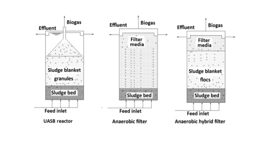
Upflow anaerobic sludge blanket reactors UASB: these are reactors that work with biomass grouped into granules, have a very high efficiency and a short hydraulic residence time when wastewater with a very high volumetric organic load value is introduced. Its design allows the reaction, sludge separation and biogas collection to be carried out in the same equipment. The main disadvantage is its sensitivity to toxic compounds, which is why it requires pretreatment when applied to the treatment of leachates.
Attached biomass systems (anaerobic)
Anaerobic filter: it is a high-performance upflow system in which biomass is retained as biofilm in a support material: for example, specially designed porous cylinders that fill the reactor body. The biogas generated is collected in structures similar to the gas collector of a UASB reactor.
Hybrid bed filter HBF: it consists of the fusion of a UASB in the lower part of the reactor and an anaerobic filter in the upper part. Optimizes liquid-biogas separation and retention of solids. This higher retention of solids results in higher biomass concentrations within the reactor and, therefore, higher process yields. The disadvantage of reactors that include a filter in their structure is the high cost of the support medium.
Generally, activated carbon is being applied for the treatment of leachates as a support medium that allows very high yields.
Figure 8. reflects a comparison of the structures of a UASB, an anaerobic filter reactor and a HBF reactor:
Fluidized bed reactor: these reactors incorporate activated carbon that floats in the reaction medium on whose surface the biomass adheres and grows. This technology makes it possible to combine adsorption and biological degradation processes to remove contaminants from leachates.
A collection of examples of real plants that treat leachates by applying anaerobic reactors in their process is collected in the following Table. The table shows the available data such as the organic load of the leachate in COD, the operating temperature and the efficiency of removal of organic load.
Table 4. Operational parameters and real plant yields treating leachates with anaerobic reactors. Adapted from Renou et al- 2008.
COD (mg/L) | BOD5/COD | T (ºC) | Performance, as pollutant removal (%) |
|---|---|---|---|
Digesters |
|
|
|
4.000 BOD5 | - | 20-25 | 96 COD and 53 BOD5 |
37.000-66.660 | 0,4-0,6 | 35 | 92,5 COD |
1.537 | - | - | 95,7 COD |
5.100-8.300 | 0,43-0,50 | 15,5-35 | 56-70 COD |
800-2.000 | - | 17 | 20 COD |
Anaerobic SBR |
|
|
|
546-5.770 TOC | 0,53 | 35 | 73,9 TOC |
15.000 | - | 40-50 | 75 COD |
5.750 | - | 25 | 62 COD |
UASB |
|
|
|
6.649-15.425 | - | - | 88 COD |
10.000-64.000 | - | 15-35 | 82 COD |
3.000-4.300 | 0,65-0,67 | 11-24 | 45-71 COD |
1.500-3.200 | 0,61-0,71 | 13-23 | 65-75 COD |
30.000 | - | 30 | 82 COD |
3.800-15.900 | 0,54-0,67 | 35 | 83 COD |
3.210-9.190 | - | 35 | 77-91 COD |
9.264-12.050 | - | 35 | 58 COD |
24.400 | - | 36 | 80-90 COD |
.5400-20.000 | - | 37-42 | 96-98 COD |
Anaerobic filter |
|
|
|
14.000 | 0,7 | 21-25 | 68-95 COD |
3.750 | 0,3 | - | 60-95 COD |
5.000-6.000 | - | 35 | 87,5 NH4+ |
HBF |
|
|
|
2.000-3.000 | 0,41-0,59 | 21 | 75 COD |
1.800 | 0,53 | 11 | 56 COD |
19.600-42.000 | - | 30 | 81-97 COD |
1.250-4.490 TOC | 0,53 | 35 | 65 TOC |
Fluidized bed reactor |
|
|
|
108 | 0,06 | 20 | 42-57 COD |
1.100-3.800 | - | 35 | 82 COD |
3.3. Physical-chemical treatments
The physical-chemical treatments of leachates consist of the reduction of total suspended solids, colloidal particles, floating material, color, odor, toxic compounds, heavy metals and refractory organic compounds (humic and fulvic acids). These processes are used within the leachate treatment train as pretreatment before biological treatments or as final polishing. Specific technologies can also be applied to eliminate a specific contaminant in a specific leachate.
Physical-chemical processes serve mainly to assist biological processes, eliminating pollutants and refractory organic compounds that could inhibit subsequent biological treatment, thus increasing the effectiveness of the treatment.
· Coagulation–flocculation
It is used as a pre-treatment prior to biological treatments or reverse osmosis systems, or as a final polishing process for the elimination of non-biodegradable material.
The process consists of the generation of aggregates by adding a coagulant, which destabilizes the loads of the suspended solids and the organic matter that they carry, in addition to embedding other pollutants in the structure of the aggregate. This organic matter also includes recalcitrant organic compounds, which is why this process allows their elimination.
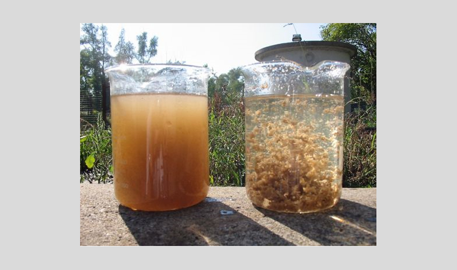
These aggregates are then put in contact with a flocculant so that the aggregates group together forming flocs that can be separated from the effluent by clarification techniques.
Some of the most commonly applied coagulating compounds are aluminum sulfate, poly aluminum chloride, ferrous sulfate or ferric chloride, although there is increasing interest in the use and optimization of natural coagulants such as tapioca flour, chickpea flour, extract of moringa oleifera or cactus extract. As for flocculant, there is a wide selection of synthetic, organic and mixed polyelectrolytes on the market.
The optimal combination of coagulant and flocculant must be carried out through Jar-Test, using samples of the water to be treated and applying different combinations of products and pH adjustment until obtaining the most favorable results in terms of elimination of solids and pollutants characteristic of the effluent.
· Clarification via flotation
Flotation is applied extensively as a clarification and separation process and focuses on the removal of suspended solids, colloids, ions, macromolecules, microorganisms and fibers and under optimal operating conditions it can remove up to 60% of refractory organic compounds.
One of the most efficient flotation processes in terms of removal performance and solids separation effectiveness is dissolved air flotation or DAF (Dissolved Air Flotation).
Electro-flotation and electro-coagulation systems: currently there is a trend in the treatment of industrial wastewater to the application of electricity in these processes with the aim of reducing the use of chemicals and increasing the yields of the process up to 96% of COD removal and 99% of solids removal in suspension in the treatment of leachate. At the moment, the biggest disadvantage of this technology is its high energy cost.
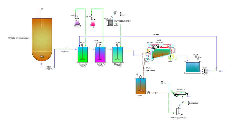
Combined DAF coagulation – flocculation and flotation application: Technology offered by SIGMA
One of the most widely applied leachate pretreatments is the combination of coagulation-flocculation followed by a DAF dissolved air flotation system. In general, this sequence allows the separation of contaminants by coagulation-flocculation and the removal of flocs and buoyant solids by applying a DAF system.
This combination of pretreatment technologies can be applied efficiently for all types of leachate. Also, a screening system can be installed prior to entering the coagulation-flocculation treatment to retain large solids.
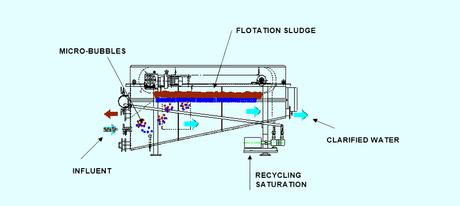
The DAF technology developed by SIGMA combines the principles of dissolved air flotation and sedimentation with an optimal equipment design.
One of the most widely applied effective operating technologies that have proven to be a very suitable pretreatment for the treatment of leachates is DAF dissolved air flotation preceded by a coagulation-flocculation process.
Coagulation is the destabilization of the polluting matter in the influent. Fine agglomerates of the residue form in the water. Next, a flocculant in the form of polyelectrolyte is dosed to increase the size of the agglomerates and group them into flocs. The flocs formed in flocculation are ideally sized to be separated from water in a SIGMA DAF dissolved air flotation unit.
SIGMA offers various designs for the flocculation coagulation process: stirred tank process or continuous process SIGMA PFL.
DAF technology is an efficient and robust separation process for oils, fats, colloids, ions, macromolecules, microorganisms and fibers.
The coagulation-flocculation sequence followed by DAF is a very common and widely used concept in leachate treatment and has proven over the years to be efficient in performance and costs, both operational and in terms of chemical and energy consumption when it is properly designed. It is an effective and robust pretreatment for the treatment of leachates, from the very young to the mature.

During DAF treatment, compressed air is introduced into a recirculating clarification stream, dissolves in the liquid medium, and subsequently generates 30-50 µm bubbles when released through a dispersion head into a DAF tank. The coagulated and flocculated particles adhere to the bubbles and float to the top of the DAF unit, where they are removed mechanically.
The sedimentable matter descends into the sediment compartment at the bottom of the DAF unit and is discharged by a sludge extraction system.
SIGMA also offers equipment for the treatment of collected sludge.
The clarified water leaves the DAF unit via an adjustable supernatant system. Part of this stream of clarified water will be redirected by the recirculation pump to enter the compression and air saturation system.
SIGMA DAF technology is currently used effectively in other application areas such as drinking water treatment, tertiary wastewater treatment, sludge thickening, filter backwash waste recovery and seawater pretreatment for desalination.
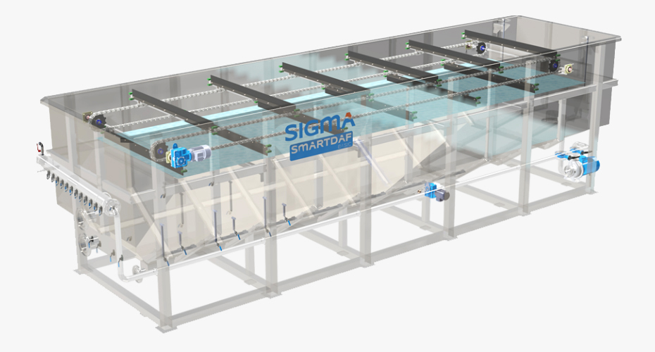
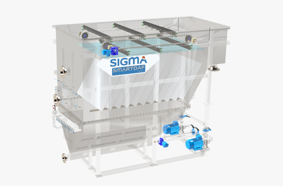
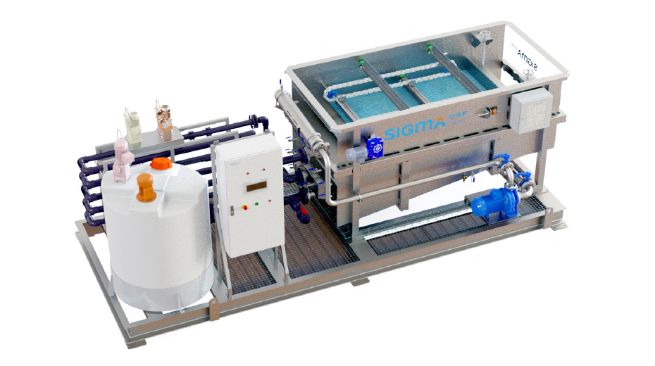
SIGMA offers a wide range of DAF flotation equipment, specially designed according to the flow to be treated and space requirements, from equipment that can treat flow rates of 5 m3/h to equipment that can treat 1,000 m3/h, compact equipment is also offered. The treatment capacity of SIGMA DAF equipment covers pollutant load ranges of up to 40 kg of solids per flotation surface.

DAF technology, coupled with properly designed coagulation-flocculation chemistry, has been shown to be effective in removing grease, oils, suspended solids, turbidity, color, some bacteria, organic matter, recalcitrant organic matter, heavy metals, and other contaminants embedded in flocs.
The advantages of SIGMA DAF systems include:
- High quality f the effluent.
- Rapid start-up.
- High rate operation.
- Thicker sludge (reduction in the volumen of produced sludge).
- Reduced footprint.
- Easy to operate.
- Robust and well-known technology.
- Simple, adaptable and efficient control systems.
The best combination of units that constitute the pretreatment and the chemicals for the coagulation-flocculation stages and the corresponding pH adjustment, must be designed based on the leachate analysis, applying Jar-Test analysis to the samples of each leachate.
AGUASIGMA offers to perform these analyzes and design the coagulation-flocculation step and pH adjustment plus the DAF design of the pretreatment chain. In our facilities SIGMA LAB we can perform Jar-Tests to analyze a wide range of wastewater.
If you want more information regarding our services, do not hesitate to contact us through the form shown on the right, by writing us an email or by calling us.
The pretreatment yields applying coagulation-flocculation followed by a DAF flotation system are between 30 - 75% removal of COD from leachates and > 90% removal in suspended solids, taking into account that this performance depends on how it is have optimized the combination of coagulant and flocculant products.
· Chemical precipitation
This process is widely used as a pretreatment for the elimination of ammonia nitrogen prior to a biological treatment. Selective ammonia nitrogen precipitation is carried out in the form of ammonium magnesium phosphate also known as MAP or struvite. This is achieved by adding a series of salts to the wastewater (MgCl2 · 6H2O and Na2HPO4 · 12H2O in a generally Mg: NH4+: PO4- ratio of 1:1:1), keeping the pH between 8.5 - 9.
The yields of this process are > 90% removal of ammonia nitrogen and up to 50% removal of COD from leachates.
· Adsorption
It consists of the adsorption (physical binding) of pollutants to an activated carbon matrix. Activated carbon can be installed in powder form (PAC) or in columns. This process makes it possible to achieve greater COD reductions than with chemical methods, but it has the disadvantage that the activated carbon has to be replaced from time to time. It is commonly used as a pretreatment prior to biological leachate treatment or to ensure a final polish by removing heavy metals and recalcitrant organic compounds.
The yields of this process applying activated carbon are between 50-70% elimination of both COD and ammonia nitrogen from the leachates.
Both powder and column activated carbon filters are commonly installed after a DAF unit to increase the efficiency of the process.
Other alternative materials to activated carbon are: zeolite, vermiculite, illite, kaolinite, activated alumina or ashes from incineration of sludge from a WWTP.
· Advanced oxidation
Oxidation is a method applied in the removal of refractory organic compounds from leachates. It is applied both as a pretreatment and as a polishing process in the final effluent. There is growing interest in advanced oxidation processes AOP which, applied to mature leachates, can:
Oxidize organic substances to carbon dioxide and water (mineralization process)
Increase the biodegradability of recalcitrant organic compounds to optimize subsequent biological treatment.
There is a great variety of chemical oxidation processes but the most commonly applied in the treatment of leachates are:
- Ozonation: application of O3, achieves yields of between 40 - 67% elimination of COD from leachates.
- Combination O3/H2O2: combination of two strong oxidants, achieves yields of between 70 - 95% COD removal from leachates.
- Combination O3/UV: application of O3 in combination with ultraviolet radiation, achieves yields of between 45 - 65% elimination of COD from leachates.
- Fenton and photo-Fenton process: oxidation by H2O2 and Fe2+, achieves yields of between 45 - 78% elimination of COD from leachates.
Main disadvantages of advanced oxidation processes are: high demand for energy and electricity and oxidative products, which increases the cost of operation; and the generation of intermediate compounds of oxidation known as free radicals that can increase the toxicity of the effluent if the addition of oxidants is not controlled correctly.
· Chlorination
Chlorination consists of putting the effluent out of the biological treatment in contact with chlorine. It is effective in the disinfection of the effluent, but this technology tends to be replaced since it supposes an unwanted discharge of chlorides in the treated water. Other alternative methods to disinfection are those described above as advanced oxidation processes.
· Stripping with air
This process is widely used in the elimination of ammonia nitrogen in the treatment of leachates. It consists of putting the leachate in contact with an ascending current of air so that the ammonia nitrogen passes into the gas phase and is eliminated by the gaseous effluent.
High pH values are applied and the resulting gases have to be properly treated as hazardous waste, cleaning them with sulfuric acid or chlorhydric acid in additional equipment. Operational problems need to be carefully controlled, for example: when calcium carbonates are used for pH adjustment, lime scale can occur in equipment and pipes, foam can also be generated within the stripping column.
The yields of this process are > 90% removal of ammonia nitrogen from the leachates.
· Ion exchange
It consists of a reversible ion exchange between the solid phase of a column and the liquid phase of the leachate in which there is no permanent change in the solid structure of the column. This treatment removes traces of heavy metals and recalcitrant organic compounds. Although it is not very widely applied in the treatment of leachate, there is a growing interest in this process.
Prior to an ion exchange column, the leachate must be subjected to a biological treatment and removal of suspended solids.
The main disadvantage of this process is its high operational cost.
3.4. Advanced treatments: membrane technologies
Advanced leachate treatments are membrane application treatments. The membranes can achieve high yields of elimination of contaminants from the leachate, they are generally applied as processes combined with biological and physical-chemical treatments, achieving in-depth and optimal treatment of the leachate.
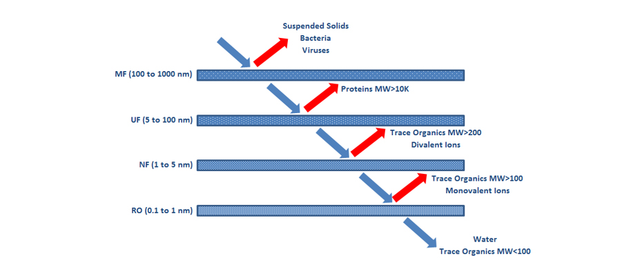
There are four types of membranes, from largest to smallest pore size: Microfiltration (MF), Ultrafiltration (UF), Nanofiltration (NF) and Reverse Osmosis (RO). In Figure 17 this classification is represented according to the pore size (in nm) and the contaminants that each type is capable of retaining.
· Microfiltration MF
MF membranes remove colloids, suspended solids, bacteria and viruses. They are generally applied as a pretreatment for other UF, NF or RO membranes or for subsequent chemical treatments in the treatment of leachate. They are not applied alone since their effectiveness is poor for the requirements of the effluent.
· Ultrafiltration UF
UF membranes consist of a selective filtration process by applying pressure of up to approximately 10 bars. These membranes eliminate high molecular weight organic macromolecules and particles, allowing the fractionation of organic matter. The effectiveness of a UF membrane is strongly dependent on the type of material the membrane is made of.
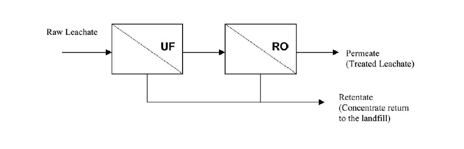
UF membranes are generally applied as a pre-filtration to optimize RO processes and prevent clogging.
UF membranes are the most commonly installed in MBR systems:
Membrane bioreactors MBR: it consists of the application of ultrafiltration membranes within the biological treatment as a means of retention of biomass. The membranes act as a separator for the sludge generated in the reactor, which implies that the installation of a subsequent clarifier is not necessary, it also prevents the loss of biomass (loss of nitrifying microorganisms and microorganisms capable of degrading slowly biodegradable organic matter), achieving very high biomass concentrations are reached within the reactor. Figures 18, 19 and 20 show diagrams of MBR reactor configurations.
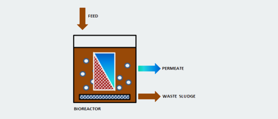

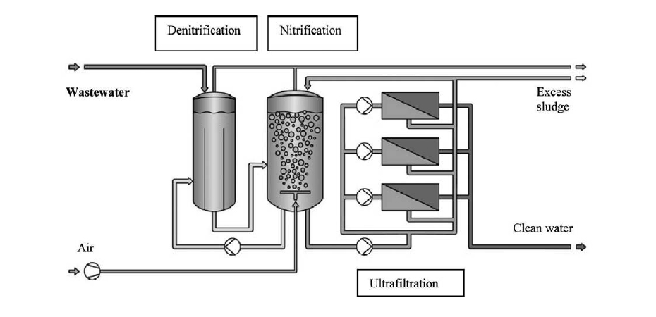
These reactors are equipment with a very high biomass concentration, very low sludge production and high pollutant removal performance. They are widely used in leachate treatment as they allow a flexible design and operation that adapts to each type of leachate. After an MBR reactor, the installation of RO membrane units is a very common practice.
Yields of an MBR are > 90% COD removal in leachate treatment.
· Nanofiltration NF
NF membranes are applied to remove recalcitrant organic matter and heavy metals in the treatment of leachates. These membranes generate very little volume of concentrate.
When NF membranes are combined with physical processes, COD reduction yields of up to 70 - 80% can be achieved.
NF membranes require careful control for clogging.
· Reverse osmosis RO
RO is a highly efficient pressure-applied technique for the purification of wastewater, including leachate. An RO process allows concentrating all dissolved and suspended solids, traces of organic compounds, heavy metals and monovalent ions.
The yields of an RO system are > 98% removal of COD and > 99% removal of heavy metals in the treatment of leachate.
The main disadvantages of an RO system are its great tendency to clogging and biofouling (so a previous treatment is necessary, such as the installation of UF membranes) and the generation of a large volume of concentrate (which has to be treated properly).
The biggest challenge today in the application of membrane technologies in the treatment of leachate is to achieve an efficiency-cost balance and to correct the problems of clogging and biofouling. The selection of cleaning products and methods is very important when designing and installing a membrane system to optimize both operational cost and performance.
Membrane Technology offered by SIGMA
SIGMA offers its membrane technology for the design and installation of Ultrafiltration, Reverse Osmosis and MBR reactors.
SIGMA DAF SMBR reactors offer the following advantages:
PLUG&PLAY solutions.
- Maximum reliability and durability.
- Constant quality of the effluent.
- It is a compact plant that allows the modular addition of UF membranes.
- Operation and control are simple and robust.
- High resistance to oxidizing agents.
SIGMA DAF SMBR plants are specifically designed for each wastewater stream to be treated. The range of capacities is between 20 - 100 m3/day.
SIGMA also offers treatment equipment for the sludge generated in the reactor.
3.5. Conclusions for the different treatments applied to leachates
- The complexity of a leachate makes it difficult to formulate general recommendations, so each leachate must be analyzed to design a specific treatment process.
- The final pollutant concentration requirements are given by local application laws.
- Until now, the combination of physical-chemical treatments in combination with biological treatments, specially designed for each leachate, has proven to be efficient and robust when it comes to meeting the discharge requirements.
- Recently, and with increasing frequency, the discharge requirements for treated leachates are more stringent in order to protect the environment and public health. In addition, the existing landfills are more mature and so are their leachates. For this reason, biological processes combined with physical-chemical processes also require the introduction of advanced or membrane processes to reach new limits.
- When membranes are installed in the leachate treatment process, it must be taken into account that concentrates require management and subsequent treatment.
- Some very common problems during the operation of a leachate treatment plant that applies a combined physical-chemical and biological process are: i) nutrient deficiency for the biological system due to the spontaneous or complementary precipitation of phosphate during the transport of the leachate or its physical-chemical treatment, ii) inhibition of the microorganisms of the biological treatment when there are peaks of ammonia nitrogen in the leachate, hence the importance of having prior homogenization systems, iii) entry of too high flow after intense periods and/or long rainfall, that is why proper management of runoff water is essential.
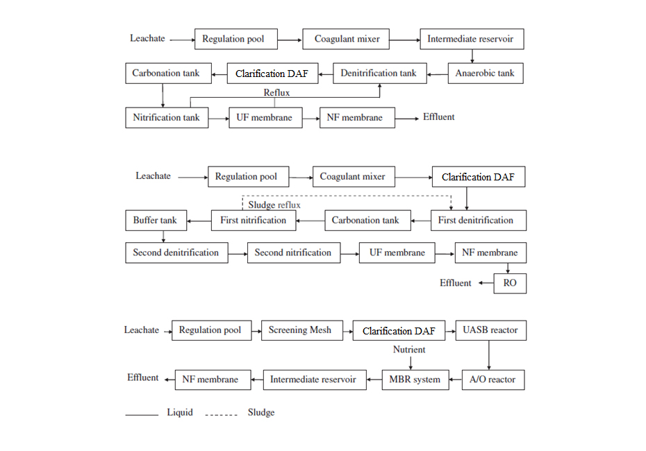
Here are some examples of plant configurations that effectively treat leachates. It is important to remember that each plant must be designed for the specific leachate to be treated, however, the sequence is common to all of them: physical-chemical pre-treatment, biological treatment that can be combined with membranes, and final polishing using physical-chemical processes and/or membrane technologies.
4. Technology applied by SIGMA to the treatment of leachate
SIGMA has experience in the installation of leachate treatment equipment. Below are several examples using the technologies described in this article.
Table 5. Design of pretreatments and complete leachate treatment carried out by SIGMA.
CASE 1: Pre-treatment | |
Origin of the water | Raw leachate, but free of sand, hydrocarbons and coarse solids |
Flowrate | 5 m3/h |
Total suspended solids | 6.000 mg/L |
Temperature | 30 ºC |
Installed technologies | ·Equalization tank |
| ·Coagulation – flocculation tanks system and pH adjustment |
| ·SIGMA DAF FPAC clarifier |
| ·UF membrane system |
Solids removal | > 90% |
|
|
CASE 2: Pre-treatment |
|
Origin of the water | Raw leachate |
Flowrate | 5 m3/h |
Total suspended solids | 1.000 mg/L, with peaks of 4.000 mg/L |
Temperature | 30 ºC |
Installed technologies | ·Equalization tank |
| ·Coagulation – flocculation tanks system and pH adjustment |
| ·SIGMA DAF FPAC clarifier |
Solids removal | > 90% |
|
|
CASE 3: Complete treatment | |
Origin of the water | Raw leachate |
Flowrate | 50 m3/day |
COD | 15.000 mg/L |
BOD5/COD | > 0,5 |
Ammonia nitrogen NH4+ | 1.600 mgN/L |
Chloride | 6.000 mg/L |
Conductivity | 25.600 µS/cm |
Installed technologies | ·Denitrification unit |
| ·Two nitrification units |
| ·UF membranes system |
| ·NF membranes system |
| ·RO membranes system |
| ·Adsorption in Activated Carbon system |
COD removal | 98,90% |
Ammonia nitrogen removal | 99,00% |
5. References
Abbas A., Jingsong G., Ping L., Ya P., Al-Rekabi W. 2009. Review on Landfill Leachate Treatment. American Journal of Applied Sciences. 6(4), 672-684.
Adlan M., Palaniandy P., Aziz H. 2011. Optimization of coagulation and dissolved air flotation (DAF) treatment of semi-aerobic lanfill leachate using response surface methodology (RSM). Desalination. 277, 74-82.
Ahn W., Kang M., Yim S., Choi K. 2002. Advanced landfill leachate treatment using an integrated membrane process. Desalination. 149, 109-114.
Amani T., Vaysi K., Dastyar W., Elyasi S. 2015. Studying interactive effects of operational parameters on continuous bipolar electrocoagulation-flotation process for treatment of high load compost leachate. Water Science & Technology. 70(8) 1314-1321
Bashir M., Aziz H., Amr S., Sethupathi S., Ng C., Lim J. 2014. The competency of various applied strategies in treating tropical municipal landfill leachate. Desalination and Water Treatment. 54, 2382-2395.
Bernardino S. 2019. Production of biogas/bioSNG from anaerobic pretreatment of milk-processing wastewater. Chapter in ‘Substitute Natural Gas from Waste. 397 – 424.
Billard H. 2001. Centre de stockage des déchets Exploitation.
Costa A., Alfaia R., Campos J. 2019, Landfill leachate treatment in Brazil - An overview. Journal of Environmental Management. 232, 110-116.
Dastyar W., Amani T., Elyasi S. 2015. Investigation of affecting parameters on treating high-strength compost leachate in a hybrid EGSB and fixed-bed reactor followed by electrocoagulation-flotation process. Process Safety and Environment Protection.
Durmusoglu E. and Yilmaz C. 2005. Evaluation and temporal variation of raw and pre-treated leachate quality from an active solid waste landfill. Water, Air and Soil Pollution. 171, 359-382.
Elyasi S., Amani T., Dastyar W. 2015. A Comprehensive Evaluation of Parameters Affecting Treating High-Strength Compost Leachate in Anaerobic Baffled Reactor Followed by Electrocoagulation-Flotation Process. Air, Water & Soil Pollution. 226, 116.
Foo K. and Hameed B. 2009. An overview of landfill leachate treatment via activated carbon adsorption process. Journal of Hazardous Materials. 171, 54-60.
Ghafari S., Aziz H., Bashir M. 2010, The use of poly-aluminium chloride and alum for the treatment of partially stabilized leachate: A comparative study. Desalination. 257, 110-116.
Hoomweg D., Bhada-Tata P. 2012. What a Waste: Waste Management Around the World. Word Bank, Washington.
ISWA. Landfill Operational Guidelines. 2019. 3rd Edition. A report from ISWA’s working group on landfill.
Keenan J., Steiner R., Fungaroli A. 1984. Landfill Leachate Treatment. Process Design.
Mohammad-pajooh E., Turcios A., Cuff G., Weichgrebe D., Rosenwinkel K., Vendenyapina M., Sharifullina L. 2018. Removal of COD and trace metals from stabilized landfill leachate by granular activated carbon (GAC) adsorption. Journal of Environmental Management. 228, 189-196.
Nath A., Mishra A., Pande P. 2020. A review natural polymeric coagulants in wastewater treatment. Materials Today: Proceedings.
Palaniandy P., Adlan M., Aziz H., Murshed M. 2010. Application of dissolved air flotation (DAF) in semi-aerobic leachate treatment. Chemical Engineering Journal. 157, 316-322.
Renou S., Givaudan J., Poulain S. Dirassouyan F., Moulin P. 2008. Landfill leachate treatment: Review and opportunity. Journal of Hazardous Materials. 150, 468-493.
Robinson A. 2015. Landfill leachate treatment. Wehrle Environmental. Membrane Technology.
STOWA Rapport 2012. Explorative Research on Innovative Nitrogen Recovery. 15.
Yao P. 2013. Perspectives on technology for landfill leachate treatment. Arabian Journal of Chemistry.
Zhang Q., Tian X., Ghulam A., Fang C., He Ruo. 2013. Investigation on characteristics of leachate and concentrated leachate in three landfill leachate treatment plants. Waste Management. 33, 2277-2286.
Zin N., Aziz H., Adlan M., Ariffin A., Yusoff M., Dahlan I. 2014. Treatability Study of Partially Stabilized Leachate by Composite Coagulant (Prehydrolyzed Iron and Tapioca Flour). International Journal of Scientific Research in Knowledge. 2(7), 313-319.
